Annotated transcription · 9 min read
How Oblique Shocks Work in Supersonic Flow
Understanding the geometry, physics, and analysis methods for shock waves that turn the flow.
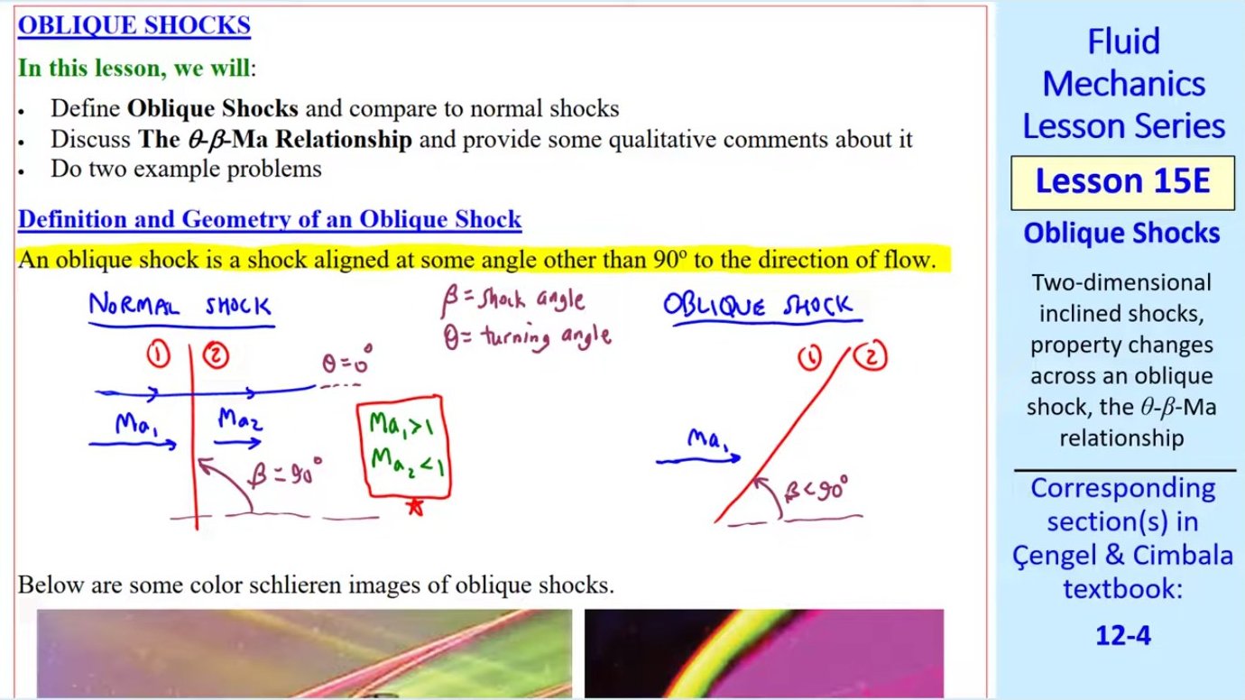
What Makes a Shock Oblique
When supersonic flow encounters a boundary at an angle, the resulting shock wave is not perpendicular to the flow direction. Instead, it forms at an oblique angle, creating what engineers call an oblique shock. Unlike the normal shocks encountered in converging-diverging nozzles, oblique shocks deflect the flow while compressing it, fundamentally changing both the speed and direction of the fluid.
Two angles define an oblique shock's geometry. The shock angle β measures the inclination of the shock wave relative to the incoming flow direction. The turning angle θ describes how much the flow deflects as it crosses the shock. For a normal shock, β = 90° and θ = 0°—the flow compresses without turning. For an oblique shock, β < 90° and θ > 0°, meaning the flow both compresses and turns.
The upstream flow must be supersonic (Ma₁ > 1), but the downstream Mach number Ma₂ can be supersonic, sonic, or subsonic depending on the shock strength. This contrasts sharply with normal shocks, which always produce subsonic downstream flow.
Velocity Components Across the Shock
The key insight for analyzing oblique shocks is that only the velocity component normal to the shock experiences compression. The tangential component—the velocity parallel to the shock—passes through unchanged. This allows engineers to treat an oblique shock as a normal shock applied only to the normal velocity component.
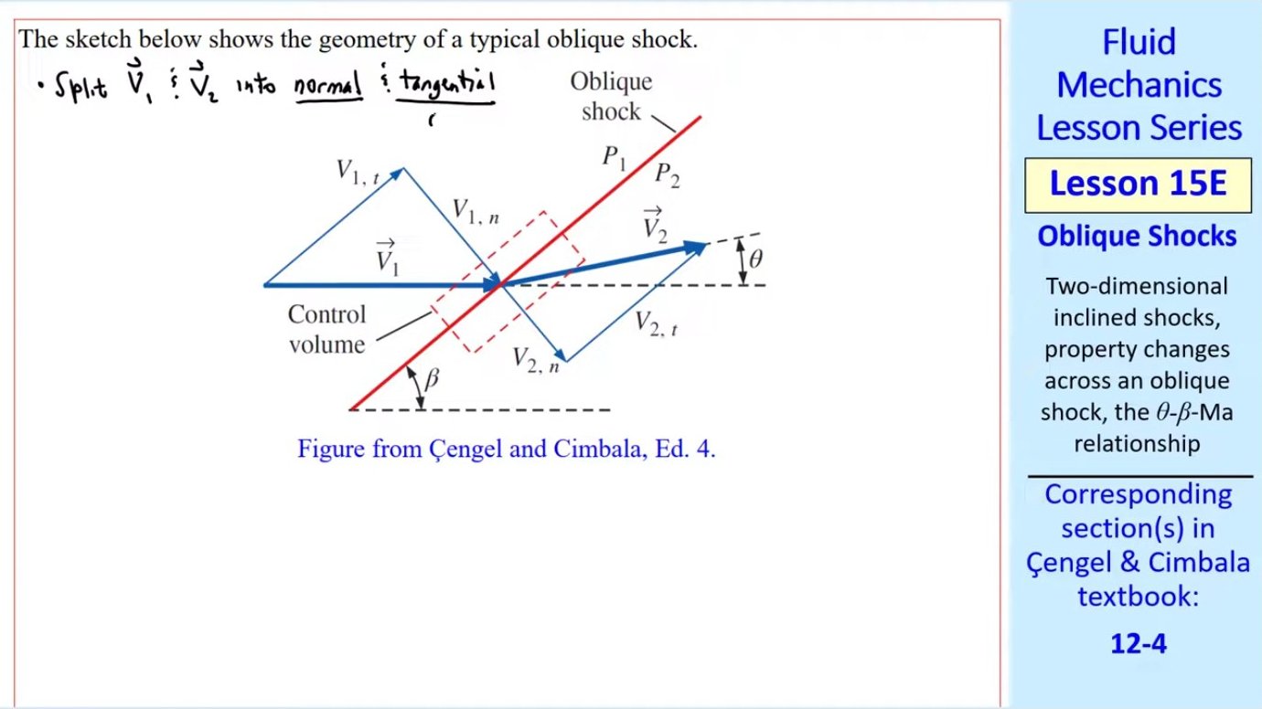
Mathematically, the upstream normal velocity is V₁,n = V₁ sin β, and the tangential velocity is V₁,t = V₁ cos β. Downstream, V₂,n = V₂ sin(β − θ) and V₂,t = V₂ cos(β − θ). The equality V₁,t = V₂,t is the first fundamental relationship for oblique shocks.
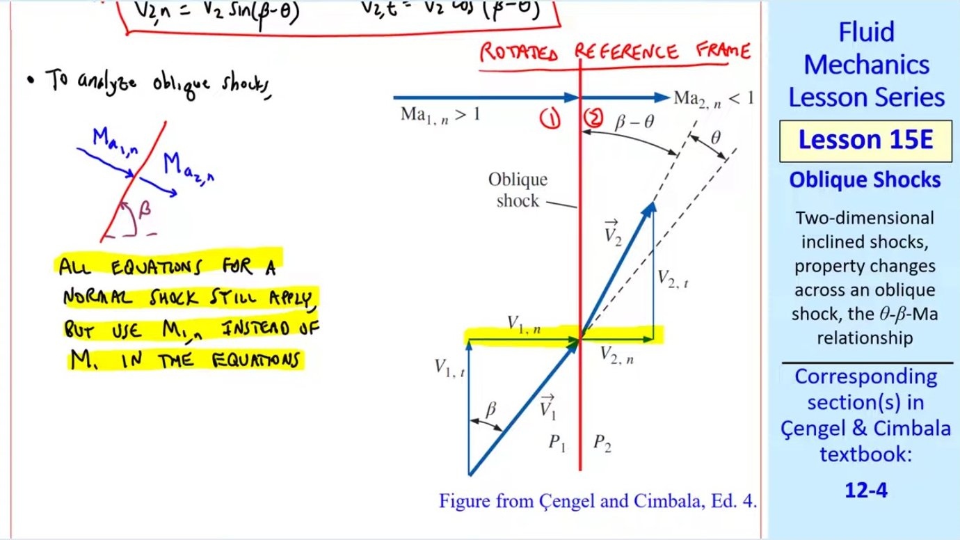
The second key relationship is that the normal components behave exactly like a normal shock. All the normal shock equations—pressure ratio, temperature ratio, density ratio, and Mach number relations—apply directly if we substitute the normal Mach number Ma₁,n = Ma₁ sin β in place of Ma₁.
The θ-β-Ma Relationship
Combining conservation laws with the velocity component relationships yields a single governing equation relating the turning angle θ, shock angle β, and upstream Mach number Ma₁. This equation also depends on the specific heat ratio k (typically 1.4 for air).
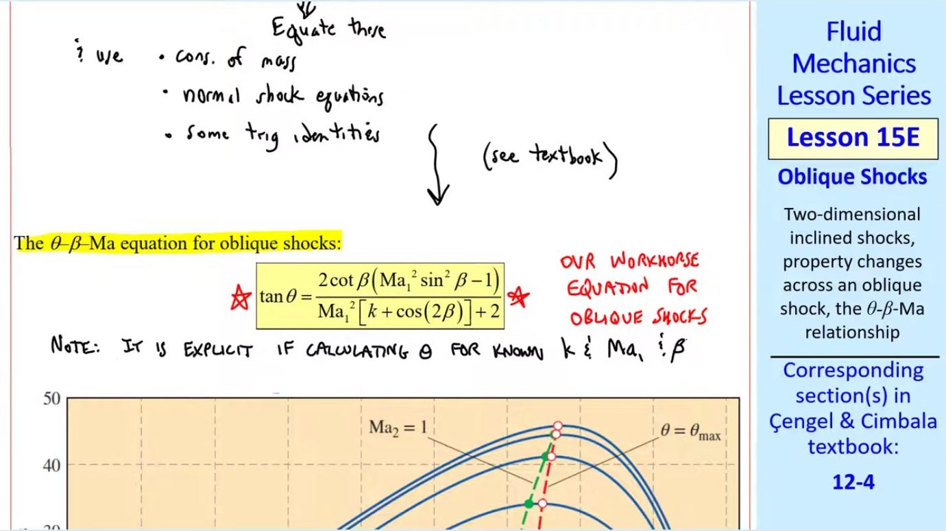
The equation is: tan θ = [2 cot β (Ma₁² sin² β − 1)] / [Ma₁²(k + cos 2β) + 2]. When shock angle and Mach number are known, this gives the turning angle directly. But when the turning angle is specified—as when flow encounters a wedge—the equation must be solved iteratively for β because it appears in multiple trigonometric terms.
The θ-β-Ma relationship reveals fundamental limits on oblique shock behavior. For any given upstream Mach number, there exists a maximum turning angle θmax beyond which an attached oblique shock cannot form. Additionally, a minimum shock angle βmin exists, below which no shock can occur. This minimum angle equals the Mach angle μ = arcsin(1/Ma₁), the angle of infinitesimally weak compression waves.
The θ-β-Ma Diagram
Plotting the θ-β-Ma equation for various Mach numbers creates a powerful design tool. Each curve represents a constant upstream Mach number, showing all possible combinations of β and θ for that Mach number. The curves grow wider and taller as Mach number increases, indicating that higher-speed flows can sustain both stronger shocks (larger β) and sharper turns (larger θ).
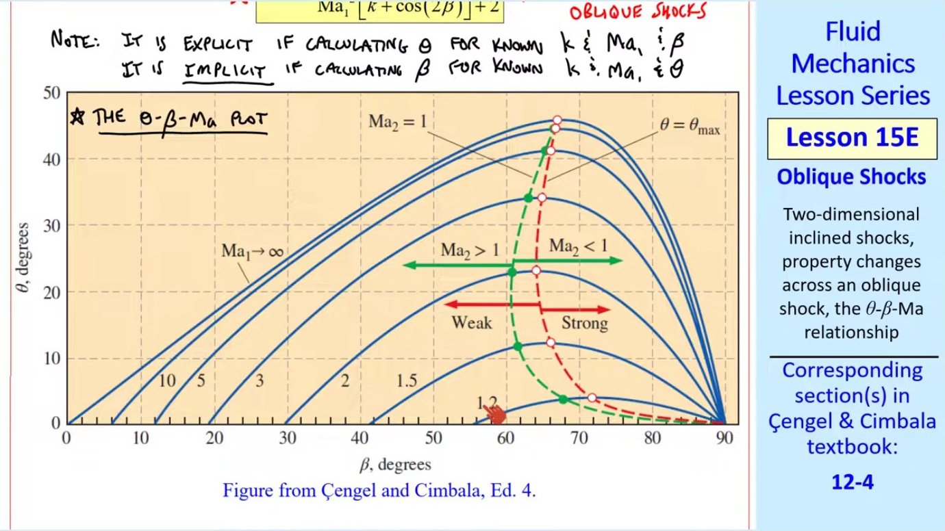
Several important features define this diagram. All curves terminate at β = 90°, the normal shock condition where θ = 0. Each curve also has a maximum value of θ, marked by the dashed red line connecting these peaks. For turning angles less than θmax, two solutions exist: a weak shock (smaller β, usually with supersonic downstream flow) and a strong shock (larger β, usually with subsonic downstream flow).
The dashed green sonic line divides the diagram into regions where Ma₂ < 1 (to the right) and Ma₂ > 1 (to the left). Strong shocks typically produce subsonic downstream flow, while weak shocks leave the flow supersonic. When the required turning angle exceeds θmax for the given Mach number, an attached oblique shock cannot form. Instead, a detached bow shock develops upstream of the body.
Physical Limits: What Happens at θmax
When a body attempts to turn the flow by more than θmax, the physics changes dramatically. An attached oblique shock cannot form because no solution to the θ-β-Ma equation exists. Instead, a curved, detached bow shock forms ahead of the body. This shock is strongest near the nose (approaching a normal shock) and weakens toward the edges.
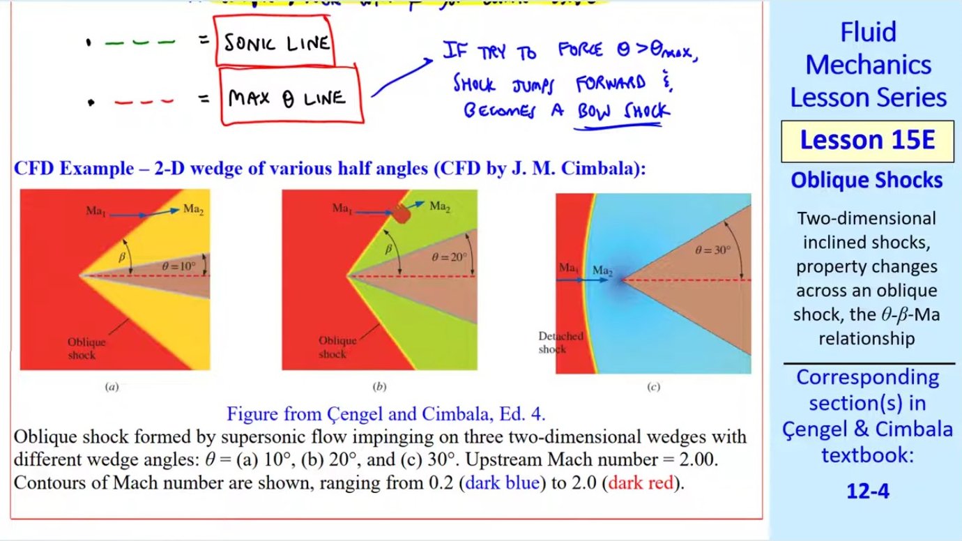
For Ma₁ = 2.0, the maximum turning angle is approximately 23°. A wedge with half-angle 10° or 20° produces a clean, straight oblique shock attached to the nose. But a 30° wedge forces a bow shock to form. The flow must decelerate through the strong central portion of the bow shock before it can navigate around the body, resulting in significantly higher drag and temperature rise.
This explains why supersonic aircraft and missiles have sharp, slender nose profiles. A sharp nose minimizes θ, keeping the shock attached and reducing drag. Blunt bodies, by contrast, always produce detached bow shocks and higher drag—acceptable for applications like reentry vehicles where high drag is actually beneficial for deceleration.
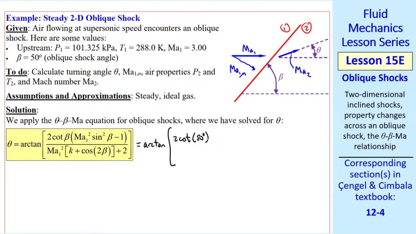
Solving Oblique Shock Problems: Given Shock Angle
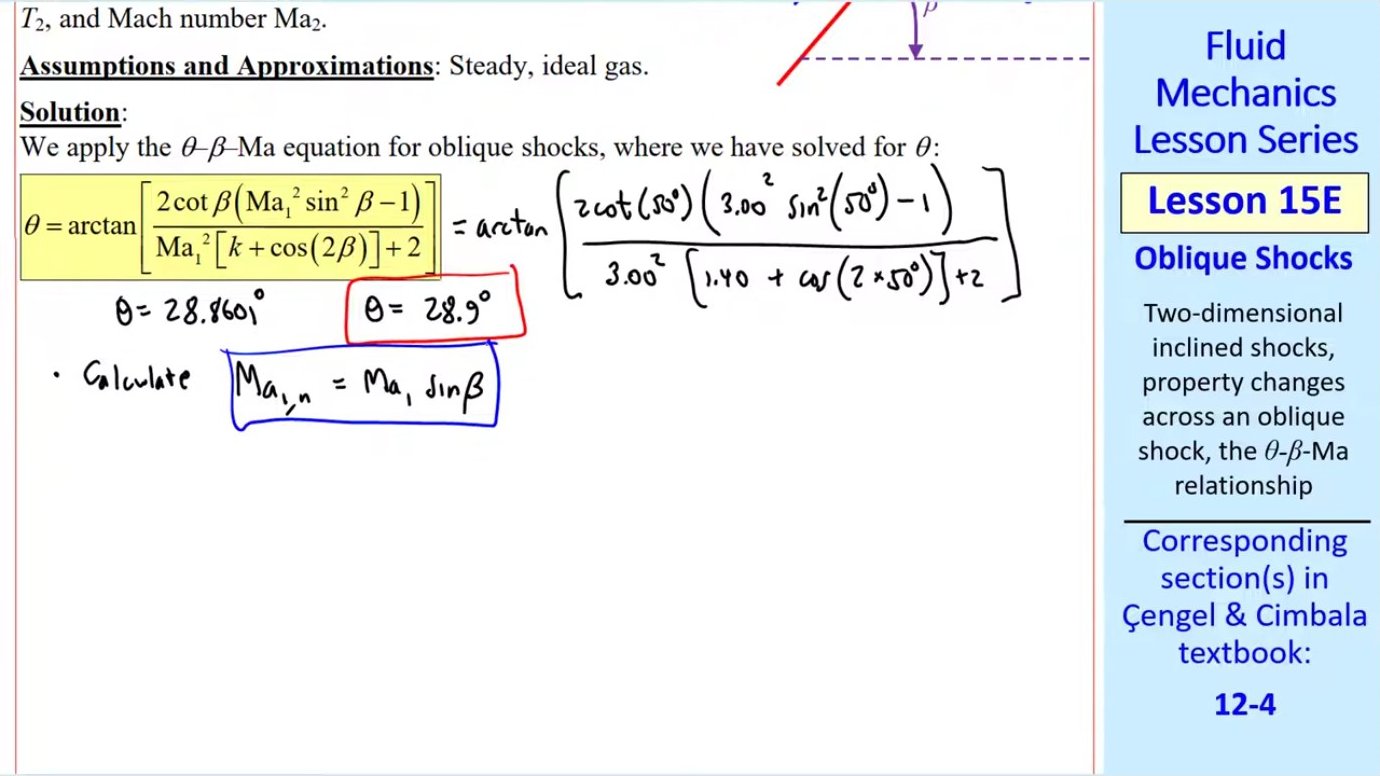
When the shock angle β is known—perhaps measured experimentally or provided as a design specification—the solution procedure is straightforward. First, calculate the turning angle θ directly from the θ-β-Ma equation. Then compute the normal component of the upstream Mach number: Ma₁,n = Ma₁ sin β.
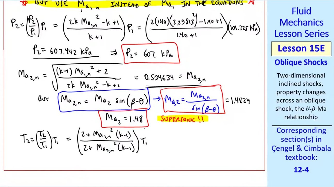
With Ma₁,n in hand, apply all standard normal shock relations—but use Ma₁,n instead of Ma₁. For example, the pressure ratio becomes P₂/P₁ = [2k Ma₁,n² − (k − 1)]/(k + 1). The temperature ratio is T₂/T₁ = [2 + (k − 1)Ma₁,n²][2k Ma₁,n² − (k − 1)]/[(k + 1)² Ma₁,n²]. The normal component of the downstream Mach number Ma₂,n comes from the normal shock Mach number relation.
Finally, convert Ma₂,n back to the actual downstream Mach number: Ma₂ = Ma₂,n / sin(β − θ). This accounts for the deflection of the flow. The full downstream velocity magnitude and direction are now known, along with pressure, temperature, and density.
Solving Oblique Shock Problems: Given Turning Angle
A more common scenario is when the turning angle is specified—for instance, by a wedge geometry—and the shock angle must be determined. This requires solving the θ-β-Ma equation iteratively for β. Methods like bisection, Newton-Raphson, or false position can converge to the solution. The equation typically yields two roots: the weak shock solution (smaller β) and the strong shock solution (larger β).
Consider Ma₁ = 3.0 and θ = 20°. Iteration finds β ≈ 37.8° (weak shock) and β ≈ 82.1° (strong shock). Both are mathematically valid solutions to the governing equation. The weak shock lies to the left of the sonic line on the θ-β-Ma diagram, indicating supersonic downstream flow. The strong shock sits to the right, producing subsonic downstream flow.
Which solution occurs in practice depends on downstream conditions. If the body narrows beyond the initial turning point, the flow tends to select the weak shock to maintain supersonic flow. If the body becomes blunter or if high back pressure exists downstream, the strong shock may form. In most external aerodynamic applications—like flow over a wedge or cone—the weak shock is observed because it minimizes entropy generation and allows the flow to remain supersonic.
Weak vs. Strong Shocks
The distinction between weak and strong shocks is not merely mathematical. Physically, the strong shock involves much greater compression, entropy increase, and total pressure loss. Pressure ratios across strong shocks can be five to ten times higher than across weak shocks for the same turning angle. Temperatures rise proportionally. The strong shock behaves more like a normal shock—its angle β is much closer to 90°.
In engineering practice, weak shocks are almost always preferred. They minimize drag, heating, and losses. Strong shocks are generally avoided except in situations where their effects are deliberately sought—such as in inlet diffusers where subsonic downstream flow is required for combustion. The downstream geometry and pressure field ultimately select which shock forms, but designers can influence this by controlling body shape and minimizing turning angles.
Practical Observations in Real Flows
Oblique shocks appear frequently in supersonic flight. Inlet ramps on jet engines use controlled oblique shocks to slow and compress incoming air efficiently. Supersonic wings generate oblique shocks at the leading edge, and careful shaping can reduce their strength and associated drag. Even the distinctive diamond-shaped shock patterns around supersonic projectiles are networks of intersecting oblique shocks and expansion fans.

Schlieren and shadowgraph imaging make shocks visible by capturing density gradients. The sharp lines in these images correspond precisely to the shock angles predicted by the θ-β-Ma equation. For simple geometries like wedges and cones, theory matches experiment remarkably well. More complex shapes produce curved shocks or shock-shock interactions, but the fundamental θ-β-Ma relationship still governs each local shock segment.
Understanding oblique shocks is essential for designing any vehicle or component operating at supersonic speeds. Whether minimizing drag on an aircraft, optimizing an engine inlet, or analyzing reentry heating, engineers rely on the principles laid out here to predict flow behavior, structural loads, and thermal environments.
Key takeaways
- → An oblique shock compresses and deflects supersonic flow, characterized by shock angle β and turning angle θ, with only the normal velocity component experiencing shock compression.
- → The θ-β-Ma equation governs oblique shock behavior and is explicit in θ but requires iterative solution for β when turning angle is specified.
- → For any upstream Mach number, a maximum turning angle θmax exists; exceeding it causes a detached bow shock instead of an attached oblique shock.
- → Two solutions often exist for a given θ: a weak shock (smaller β, usually supersonic downstream) and a strong shock (larger β, usually subsonic downstream).
- → Oblique shock analysis uses normal shock equations applied to the normal Mach number Ma₁,n = Ma₁ sin β, with tangential velocity remaining constant across the shock.
- → The θ-β-Ma diagram is a key design tool, showing feasible shock angles, separating weak/strong and supersonic/subsonic regimes, and identifying limits like θmax and βmin.
- → In practice, weak shocks are preferred for efficiency, while strong shocks cause higher drag, heating, and losses but may be necessary in specific applications like engine inlets.