Annotated transcription · 9 min read
Rayleigh Flow: How Heat Transfer Transforms Compressible Duct Flow
Understanding the thermodynamic and fluid mechanics principles when heat is added to or removed from gas flowing through a constant-area duct.
What is Rayleigh Flow?
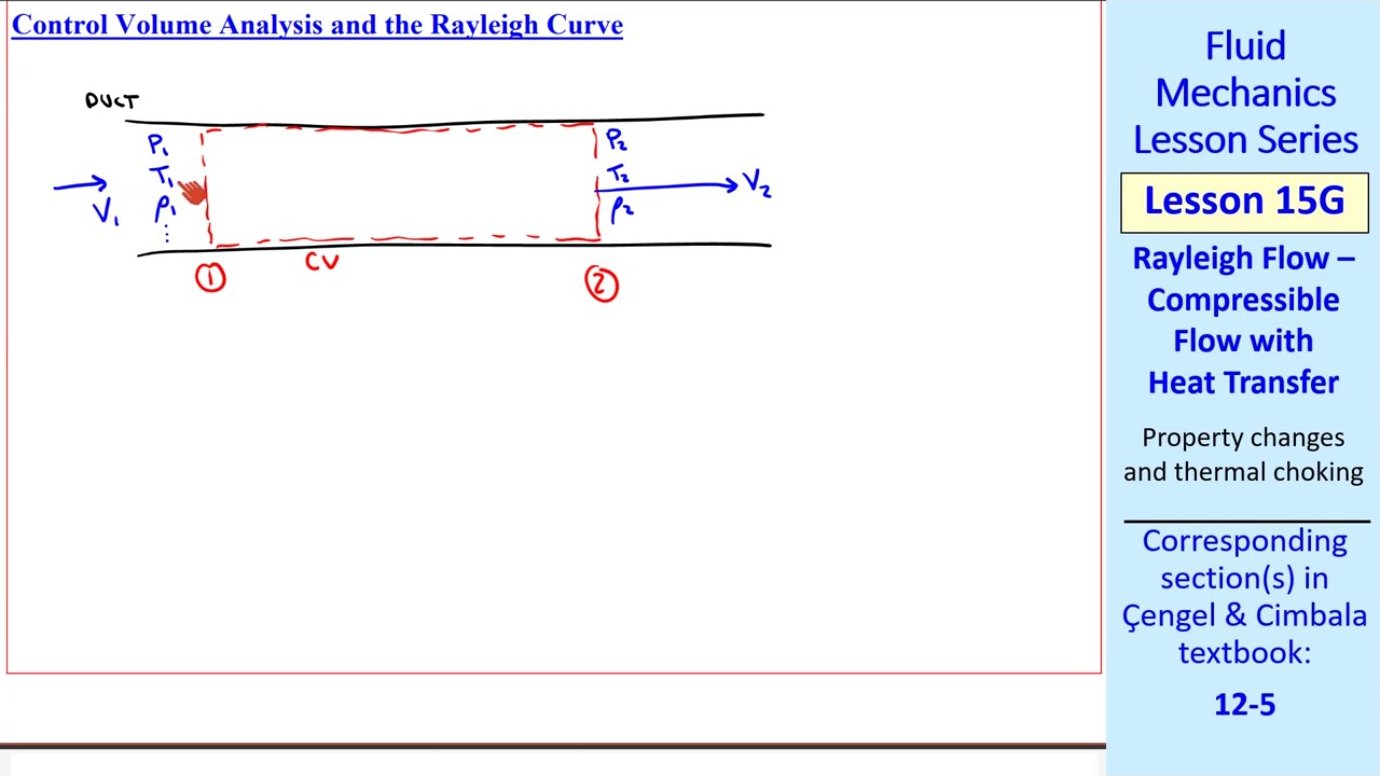
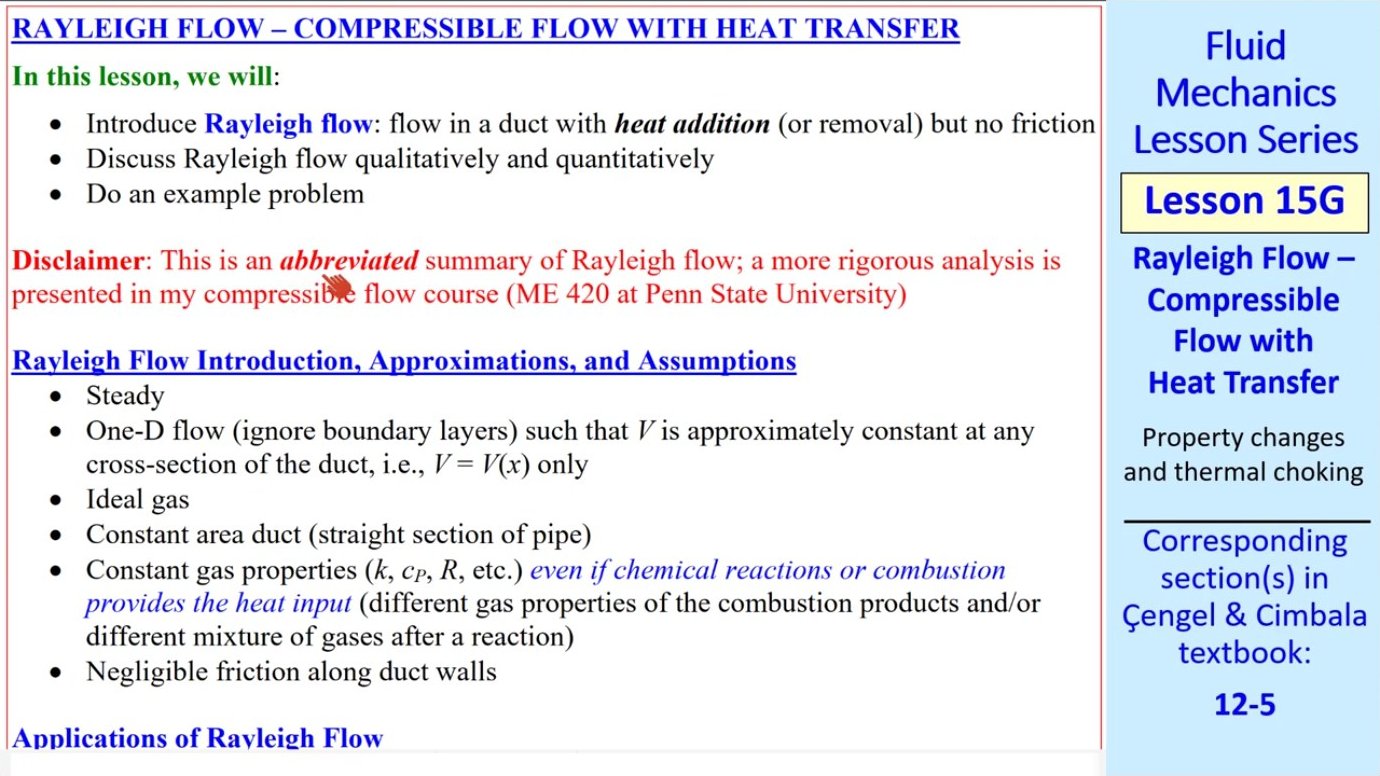
Rayleigh flow describes the behavior of a compressible gas moving through a constant-area duct when heat is added to or removed from the flow, but wall friction is negligible. Named after the physicist who first analyzed this situation, the model simplifies many real-world scenarios—such as combustion chambers in jet engines or industrial heat exchangers—into a tractable set of equations. The defining characteristic is that thermal energy changes the gas properties without the complications of varying cross-sections or viscous drag.
This idealization rests on several assumptions: the flow must be steady and one-dimensional, the gas behaves ideally with constant specific heats, the duct has uniform cross-sectional area, and friction along the walls can be ignored. While no real system perfectly satisfies all these conditions, many practical devices come close enough that Rayleigh flow provides useful engineering predictions.
Practical Applications in Engineering Systems
Rayleigh flow theory applies wherever gas flows through relatively short ducts with significant heat transfer but minimal friction. Gas heat exchangers are a prime example: tubes carrying hot or cold gases over short distances exchange thermal energy with surrounding fluids or walls. Because the tubes are brief, friction effects remain small compared to the thermal changes.

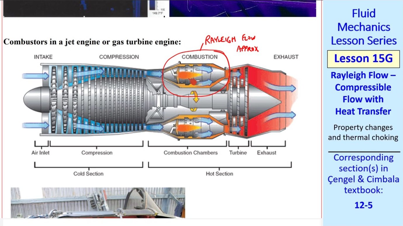
Combustion chambers in gas turbine and jet engines represent another important application. Inside the combustor, fuel burns and releases energy directly into the flowing air. Although combustion changes the gas composition, engineers approximate the mixture as having constant average properties. The chamber's short length and relatively constant diameter justify neglecting friction, so the Rayleigh model captures the essential pressure, temperature, and velocity changes as heat floods into the flow.
Conservation Principles and Governing Equations
Analyzing Rayleigh flow begins with the fundamental conservation laws. Mass conservation in a steady duct flow requires that the mass flow rate remain constant at all cross-sections. Since the area is uniform, this means the product of density and velocity must be identical at any two stations along the duct: ρ₁V₁ = ρ₂V₂. This simple relationship links how density and velocity trade off as the flow evolves.
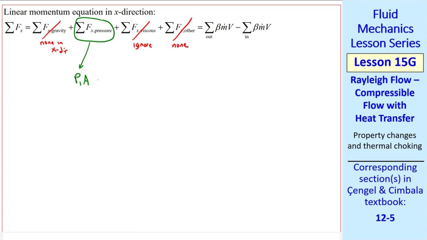
Momentum conservation in the streamwise direction yields a relationship between pressure and momentum flux. With no body forces or wall shear, the sum of static pressure and dynamic pressure (ρV²) remains constant along the duct: P₁ + ρ₁V₁² = P₂ + ρ₂V₂². This equation resembles Bernoulli's principle but applies to compressible flow. It reveals that adding heat—which accelerates the gas—must reduce static pressure to maintain momentum balance.
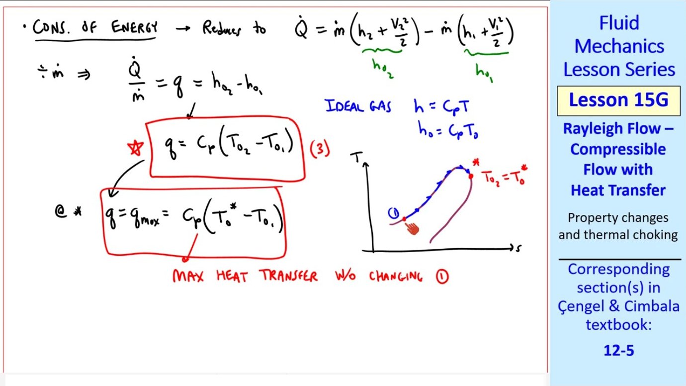
Energy conservation introduces the heat transfer term explicitly. The steady-flow energy equation states that the heat added per unit mass equals the change in stagnation enthalpy. For an ideal gas with constant specific heat, this simplifies to q = cₚ(T₀₂ - T₀₁), where q is the heat transfer per unit mass and T₀ represents stagnation temperature. This equation directly ties the amount of heat added to the resulting temperature rise or fall.
The Rayleigh Curve on a T-s Diagram
Combining mass, momentum, and energy equations with the ideal gas law and isentropic relations produces a curve on a temperature-entropy diagram known as the Rayleigh curve. For any given initial state, this curve maps out all possible downstream states achievable by adding or removing heat while maintaining the same mass flow rate and duct area. The curve has two branches: an upper subsonic branch and a lower supersonic branch.
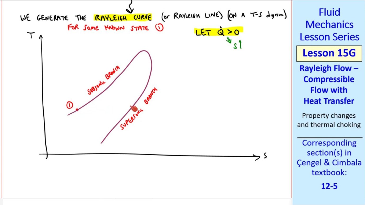
Starting from a subsonic state and adding heat, entropy must increase because heat transfer into the gas is inherently irreversible in the absence of other losses. The flow therefore moves rightward along the curve. Temperature initially rises, but as the Mach number approaches unity, the curve bends over. Eventually, at maximum entropy, the flow reaches Mach one—the sonic or critical state. This point represents a choking condition: no additional heat can be added without fundamentally changing the inlet conditions.
A counterintuitive phenomenon occurs on the subsonic branch just before choking. After temperature reaches a local maximum, continued heat addition actually decreases temperature while Mach number continues rising toward one. This 'strange zone' arises because the gas accelerates so rapidly that the kinetic energy increase outpaces the thermal energy input, pulling down the static temperature even as stagnation temperature climbs.
Maximum Heat Transfer and Choking
For any given inlet state, there exists a maximum amount of heat that can be transferred before the flow chokes. This limit corresponds to driving the exit Mach number to exactly one. The maximum heat transfer per unit mass is q_max = cₚ(T₀* - T₀₁), where T₀* denotes the stagnation temperature at the sonic reference state. Attempting to add more heat than q_max forces the inlet conditions to shift, generating an entirely new Rayleigh curve.
The same choking principle applies to supersonic inlet flows. On the lower branch of the Rayleigh curve, adding heat decreases the Mach number, again moving the flow toward the sonic point. Whether starting subsonic or supersonic, the end state of maximum heating converges on Mach one. This universality simplifies analysis: engineers know any heat addition process must terminate at sonic flow if carried far enough.
Property Ratios and Reference States
Solving Rayleigh flow problems involves algebraic manipulation of the conservation equations along with ideal gas and isentropic relations. Rather than derive new formulas for every scenario, it proves more efficient to express all properties as ratios relative to their values at the sonic reference state (denoted with an asterisk). Ratios such as T/T*, P/P*, and ρ/ρ* depend only on the local Mach number and the gas specific heat ratio k.
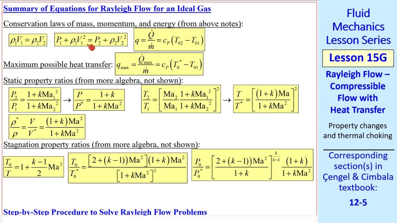
Stagnation properties also have ratio equations. For instance, T₀/T₀* involves a slightly more complex expression than the static temperature ratio, but the principle remains the same: relate the unknown stagnation temperature at any station to the known sonic reference value through Mach number. Similarly, stagnation pressure ratio P₀/P₀* captures how total pressure changes with heating, even though static pressure behavior differs markedly.
Step-by-Step Solution Procedure
A systematic approach streamlines Rayleigh flow calculations. Begin with known inlet conditions—pressure, temperature, velocity—and the specified heat transfer rate. First, use the energy equation q = cₚ(T₀₂ - T₀₁) to find the downstream stagnation temperature T₀₂. This step is straightforward algebra once the mass flow rate converts the total heat transfer rate into heat per unit mass.
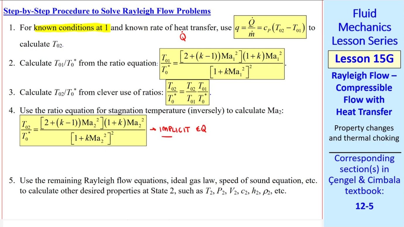
Next, compute the inlet stagnation temperature ratio T₀₁/T₀* using the known inlet Mach number. From this ratio and the inlet temperature, extract the reference sonic stagnation temperature T₀*. Then form the ratio T₀₂/T₀* by dividing the already-known T₀₂ by T₀*. This ratio feeds into the stagnation temperature relation, which can be inverted—often requiring iterative numerical methods—to solve for the exit Mach number Ma₂.
Once Ma₂ is known, all other exit properties follow from the ideal gas law, speed of sound equation, and the various ratio formulas. Static temperature, static pressure, density, and velocity can all be computed. The final check ensures that the applied heat transfer does not exceed q_max, confirming the flow has not choked unless intended.
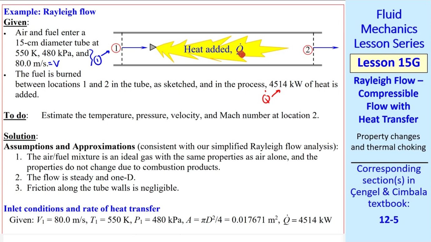
Worked Example: Combustion in a Tube
Consider air and fuel entering a round tube at 550 K, 480 kPa, and 80 m/s. The tube diameter is 15 cm, and combustion releases 4514 kW of heat. The task is to find temperature, pressure, velocity, and Mach number downstream. Treating the mixture as air with constant properties exemplifies the Rayleigh approximation.
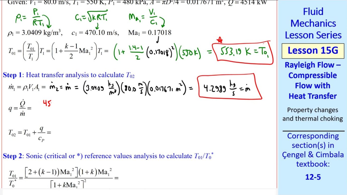
First, compute inlet density from the ideal gas law, then the speed of sound, yielding an inlet Mach number of approximately 0.17—comfortably subsonic. Stagnation temperature at the inlet follows from the isentropic relation. With density, velocity, and area known, the mass flow rate is determined. Dividing the total heat transfer by mass flow rate gives heat transfer per unit mass, which then enters the energy equation to calculate the exit stagnation temperature.
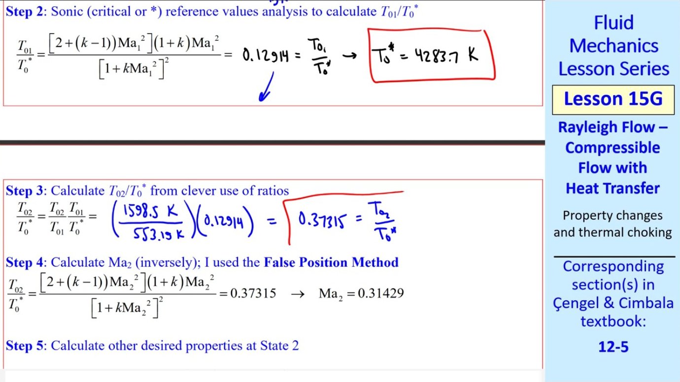
The sonic reference temperature T₀* comes from the inlet stagnation temperature ratio formula. Using this reference value, the exit ratio T₀₂/T₀* is computed. Plugging this ratio into the stagnation temperature relation produces an equation in Ma₂ that must be solved numerically. An iterative solver returns Ma₂ ≈ 0.314, still subsonic but noticeably higher than the inlet Mach number.
Before finalizing results, verify that the actual heat transfer is less than the maximum allowable. Computing q_max confirms it exceeds the 4514 kW applied, so the flow has not choked. Finally, static properties at the exit—temperature, pressure, and velocity—are extracted from the Mach number and stagnation quantities, yielding T₂ = 1570 K, P₂ = 439 kPa, and V₂ = 249 m/s.
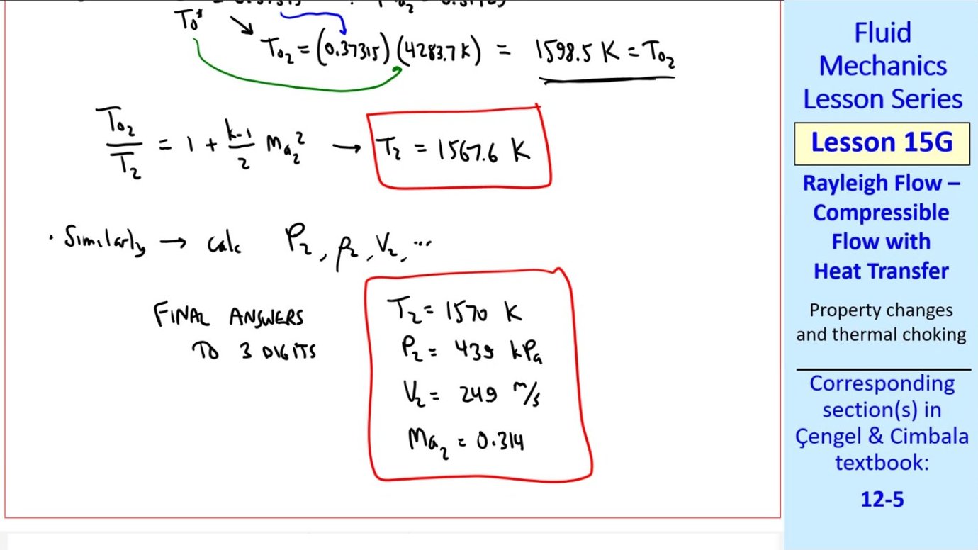
The solution illustrates characteristic Rayleigh flow behavior. Heat addition accelerates the flow and raises stagnation temperature, while static pressure must fall to satisfy momentum conservation. The Mach number increases but remains well below unity, indicating the duct could accept additional heat before choking occurs.
Key takeaways
- → Rayleigh flow models compressible gas flowing through a constant-area duct with heat transfer but negligible friction, applicable to heat exchangers and combustion chambers.
- → Mass, momentum, and energy conservation combine with ideal gas relations to produce the Rayleigh curve on a temperature-entropy diagram, linking all achievable flow states.
- → Adding heat to subsonic flow increases Mach number toward unity; adding heat to supersonic flow decreases Mach number toward unity—both processes lead to thermal choking at Ma = 1.
- → A maximum heat transfer exists for any inlet condition, beyond which the flow chokes and inlet conditions must adjust, preventing further downstream heating without upstream changes.
- → Property ratios relative to sonic reference conditions simplify calculations, and a systematic five-step procedure solves for downstream state given inlet conditions and heat transfer rate.
- → Real applications—from jet engine combustors to industrial heat exchangers—benefit from Rayleigh flow predictions when ducts are short enough that friction remains secondary to thermal effects.
- → Static temperature can decrease even while heat is added near the choking point, a counterintuitive result arising from rapid acceleration and the shift of thermal energy into kinetic energy.