Annotated transcription · 12 min read
Calculating the Aerodynamic Center of Complex Wing Planforms
A practical approach to finding the mean aerodynamic chord and center of pressure for multi-section aircraft wings.
The Relationship Between Drag and Lift
Aircraft drag can be decomposed into two fundamental components: profile drag and induced drag. The total drag coefficient is expressed as the sum of these two effects, where the profile drag coefficient represents the zero-lift drag of the airframe, and the induced drag varies with the square of the lift coefficient. This induced component arises directly from the generation of lift itself—a fundamental constraint of subsonic aerodynamics.
The induced drag correction factor, denoted k, depends on both the wing's aspect ratio and a parameter called the Oswald efficiency factor. This efficiency factor, symbolized as e, quantifies how closely a given wing's lift distribution approaches the ideal elliptical distribution. For a true elliptical planform, the Oswald efficiency equals unity, representing the theoretical minimum of induced drag for a given lift and aspect ratio.

Why Planform Geometry Matters
The shape of a wing's planform—the outline you'd see looking down from above—profoundly influences how lift distributes along the span. For a simple rectangular wing, the lift per unit span remains relatively constant across most of the wingspan, dropping off sharply near the tips. An elliptical planform, by contrast, produces a smooth elliptical lift distribution that minimizes the energy wasted in trailing vortices.
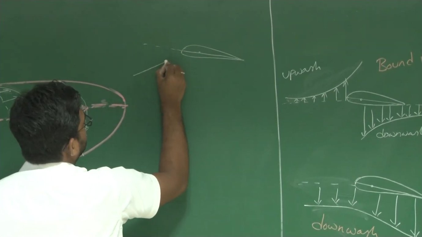
This distribution difference matters because the trailing vortex system induces a downward component of velocity across the wing. This induced downwash effectively rotates the local relative wind at each spanwise station, reducing the effective angle of attack and tilting the local lift vector slightly aft. That aft component is the induced drag—an unavoidable penalty of finite-span flight.

The Oswald efficiency factor serves as a figure of merit, comparing any real wing's performance to the ideal elliptical case. Rectangular and tapered wings typically exhibit efficiency values between 0.7 and 0.95, depending on aspect ratio and taper ratio. Designers use this single parameter to capture complex three-dimensional flow effects in preliminary sizing calculations.
From Airfoil to Wing: The Three-Dimensional Effect
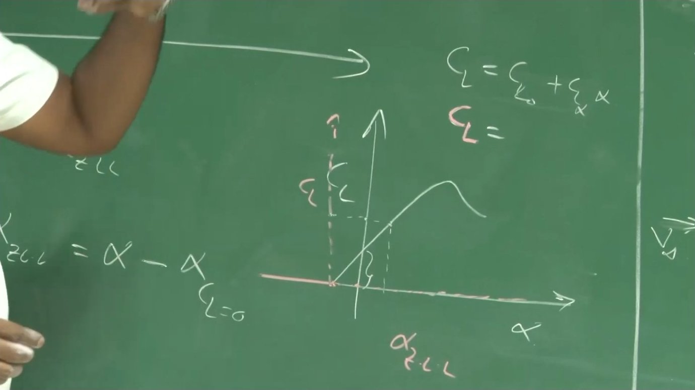
A finite wing does not perform identically to the two-dimensional airfoil from which it's constructed. The same lift coefficient that an isolated airfoil achieves at a given angle of attack requires a higher angle when that airfoil is part of a finite wing. This difference arises entirely from the induced angle of attack—the local flow deflection caused by the trailing vortex system.
Lifting-line theory provides a rigorous framework for relating two-dimensional airfoil characteristics to three-dimensional wing performance. The theory models the wing as a bound vortex at the quarter-chord line, with trailing vortices extending downstream to infinity. This vortex system induces velocities throughout the flow field, including an upwash ahead of the wing and a downwash behind and across the span.
The mathematical result is elegant: the three-dimensional lift-curve slope equals the two-dimensional slope divided by a factor that depends on aspect ratio and Oswald efficiency. For typical aspect ratios between 5 and 10, this means the wing's lift curve is noticeably shallower than the airfoil's, requiring 10 to 20 percent more angle of attack to reach the same lift coefficient.
Defining the Mean Aerodynamic Chord
For any wing planform more complex than a simple rectangle, engineers need a characteristic reference length for aerodynamic calculations. The mean aerodynamic chord (MAC) serves this purpose. It is not simply the average chord length, but rather a weighted average that accounts for how lift distributes spanwise.
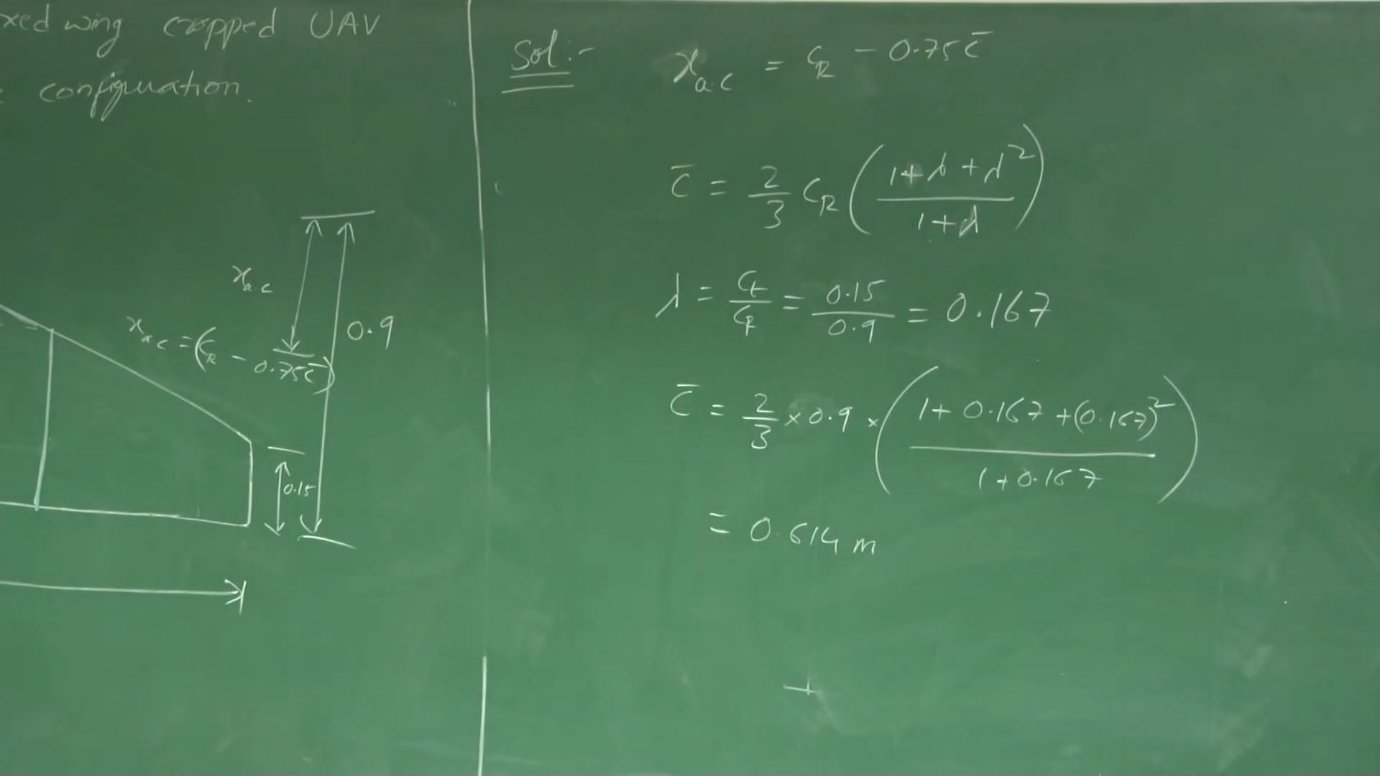
For a trapezoidal planform with root chord CR and taper ratio λ (tip chord divided by root chord), the mean aerodynamic chord is given by a specific formula involving the taper ratio. This chord length can be thought of as the chord of an equivalent rectangular wing that would produce the same pitching moment characteristics.
The spanwise location of the MAC is equally important. For a tapered wing, this position lies inboard of the geometric midspan, shifted toward the root due to the higher local chord lengths there. Standard formulas express this location as a fraction of the semispan, again dependent on the taper ratio.
Locating the Aerodynamic Center
The aerodynamic center represents the point about which the pitching moment coefficient remains constant with angle of attack. For stability and control analysis, this is the natural reference point for moment calculations. In subsonic flow, the aerodynamic center of a wing lies at approximately the quarter-chord of the mean aerodynamic chord.
To find the longitudinal position of this point relative to the wing root leading edge, one first calculates the MAC, then projects it onto the root chord plane. The aerodynamic center lies 25 percent aft of the MAC leading edge. The distance from the root leading edge to this point is therefore the root chord minus 0.75 times the MAC.
This calculation becomes essential when determining the center of gravity limits for an aircraft. The distance between the center of gravity and the aerodynamic center, expressed as a fraction of MAC, determines the aircraft's static margin—a key stability parameter that must fall within specific bounds for safe flight.
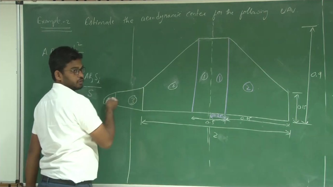
Working Example: Cropped Delta Configuration
Consider a fixed-wing UAV with a cropped delta planform. The root chord measures 0.9 meters, the tip chord 0.15 meters, and the span 1.5 meters. To find the aerodynamic center, one begins by calculating the taper ratio: 0.15 divided by 0.9 equals approximately 0.167.
Applying the MAC formula for a trapezoidal wing yields approximately 0.614 meters. The planform area, calculated as the average of root and tip chords multiplied by span, comes to roughly 0.787 square meters. From these values, the aspect ratio—span squared divided by area—works out to 2.85.
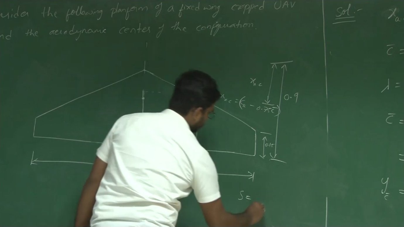
The aerodynamic center position follows directly: 0.9 meters (root chord) minus 0.75 times 0.614 meters (three-quarters of MAC) equals approximately 0.44 meters from the nose. This single number tells designers where the pitch moment characteristics will remain stable across the angle-of-attack range, informing both CG placement and control surface sizing.
Multi-Section Planforms and Weighted Averages
Real aircraft wings often feature more than one taper ratio along the span. A typical configuration might include a constant-chord center section for structural efficiency, followed by a tapered outer panel to reduce tip weight. Some designs add an elliptical tip for further drag reduction.
For such multi-section planforms, the overall mean aerodynamic chord emerges from a weighted average. Each section contributes its own MAC and area; the composite MAC equals the sum of individual MAC-area products divided by total area. The same approach applies to aspect ratio when dealing with sections of differing taper.
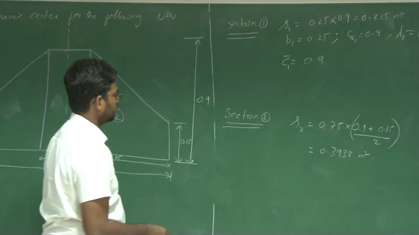
In a worked example, a UAV wing combines a 0.25-meter constant-chord section (λ = 1) with a 0.75-meter tapered section (λ = 0.167). The constant section's MAC equals its chord: 0.9 meters. The tapered section's MAC, calculated as before, comes to 0.614 meters. Weighting by their respective areas—0.225 and 0.394 square meters—yields a composite MAC of 0.718 meters.
The effective aspect ratio for the complete planform uses a similar area-weighted formula. Each section's local aspect ratio, multiplied by its area fraction, contributes to the total. This approach extends naturally to any number of sections, making it applicable to highly complex planforms including those with compound tapers or blended wing-body configurations.
Handling Elliptical and Compound Geometries
When a planform includes an elliptical section, determining the effective tip chord requires a geometric construction. The designer extends the taper line from the adjacent trapezoidal section until it intersects the spanwise location where the ellipse ends. This intersection point defines a virtual tip chord for calculation purposes.
The elliptical section can then be approximated as a tapered section with this virtual tip chord. While not perfectly accurate, this method provides sufficient precision for preliminary design and performance estimation. More refined analysis would employ numerical integration or panel methods to capture the true elliptical geometry.
Practical Implications for Design
The aerodynamic center location directly influences aircraft stability. An aft center of gravity relative to the aerodynamic center produces positive static stability—the aircraft naturally returns to trimmed flight after a disturbance. Moving the CG forward increases this stability but requires larger tail forces for control.
Designers typically specify allowable CG ranges as percentages of MAC, measured aft from the leading edge of the MAC. A light aircraft might permit 15 to 30 percent MAC, while a transport might allow 10 to 40 percent. These limits ensure adequate stability across all loading conditions while preserving controllability.
The aspect ratio and Oswald efficiency calculations inform fuel efficiency estimates. Higher aspect ratios reduce induced drag at a given lift coefficient, directly improving the lift-to-drag ratio. But structural weight penalties eventually offset aerodynamic gains, creating an optimization problem where wing geometry trades performance against mass and manufacturing complexity.
Key takeaways
- → Total drag separates into profile drag and induced drag, with induced drag proportional to lift coefficient squared and inversely proportional to aspect ratio and Oswald efficiency.
- → The Oswald efficiency factor (e ≤ 1) compares any wing's lift distribution to the ideal elliptical distribution, with elliptical planforms achieving e = 1 and minimum induced drag.
- → Three-dimensional wings require higher angles of attack than their constituent airfoils to achieve the same lift coefficient, due to induced downwash from the trailing vortex system.
- → The relationship CL_α(3D) = Cl_α(2D) / [1 + Cl_α(2D)/(π·e·AR)] connects airfoil data to finite-wing performance for preliminary design.
- → Mean aerodynamic chord (MAC) represents a weighted average chord that captures pitching moment characteristics, not simply the geometric average of root and tip chords.
- → The aerodynamic center lies at approximately 25% of MAC, and its distance from the root leading edge equals the root chord minus 0.75 times MAC.
- → Multi-section planforms require weighted averaging of individual section parameters by area to determine overall MAC and effective aspect ratio.