Annotated transcription · 12 min read
Understanding Thrust Requirements and Flight Stability in Aircraft Design
How equations of motion reveal the minimum power needed for level flight and why some velocities are safer than others.
Forces Acting on an Aircraft in Flight
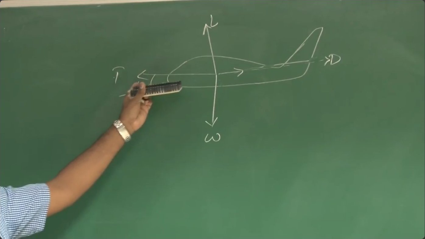
Any aircraft in flight experiences four primary external forces: thrust propelling it forward, weight pulling it downward, lift opposing weight, and drag resisting motion. Understanding how these forces interact is fundamental to designing unmanned aerial vehicles that can complete their missions efficiently.
When analyzing aircraft performance, engineers treat the vehicle as a point mass acted upon by these forces. The thrust vector typically aligns with the fuselage reference line, though misalignment can occur. Weight always acts perpendicular to the local horizontal. Lift and drag depend on the aircraft's velocity through the air, acting perpendicular and parallel to the flight path, respectively.
Flight Path Angle and Aircraft Orientation
The flight path angle, denoted gamma, measures the angle between the aircraft's velocity vector and the local horizontal. This angle differs from the angle of attack, which measures the orientation of the fuselage reference line relative to the oncoming airflow. The total pitch attitude of the aircraft equals the sum of these two angles.
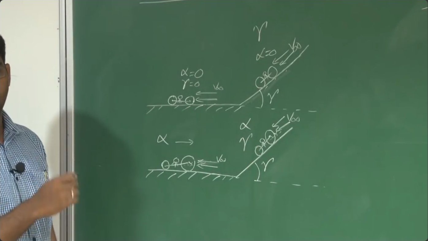
A simple analogy clarifies this distinction. Imagine riding a bicycle with equal-sized wheels on level ground. The frame sits parallel to the road, the velocity vector is horizontal, and both flight path angle and angle of attack are zero. Now ascend a ramp inclined at some angle. The velocity vector tilts upward by that same angle—the flight path angle—but if the wheels remain equal, the frame stays parallel to the slope and angle of attack remains zero.
Replace the bicycle with one having a larger front wheel. On level ground, the frame tilts nose-up relative to the velocity vector, creating a positive angle of attack even though the flight path angle remains zero. This demonstrates that an aircraft can fly with significant angle of attack during perfectly level flight.
Equations of Motion in the Vertical Plane
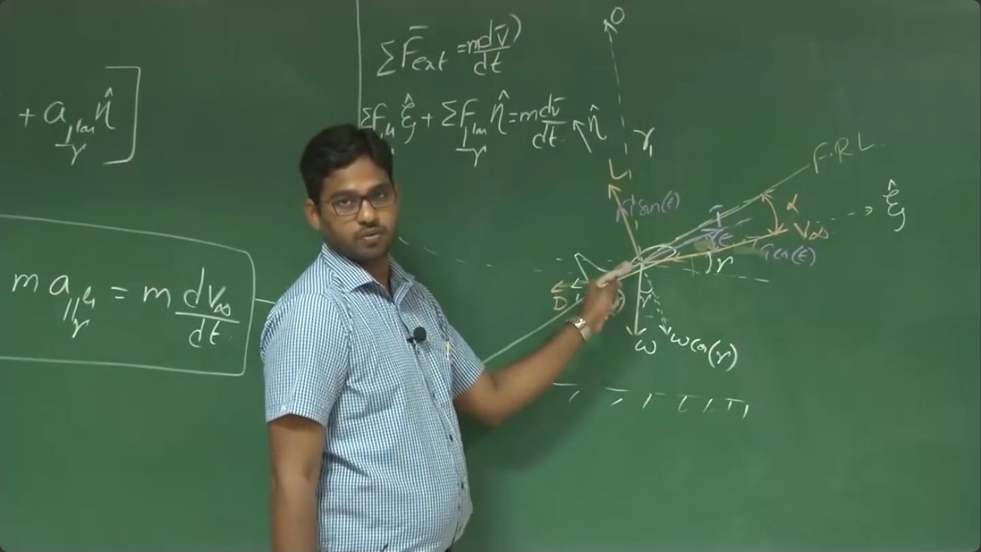
To quantify aircraft performance, engineers derive equations of motion by applying Newton's second law along and perpendicular to the flight path. The sum of forces parallel to the velocity vector equals mass times acceleration along that direction. The sum of forces perpendicular to the velocity equals mass times centripetal acceleration if the aircraft follows a curved path.

When thrust is misaligned from the velocity vector by angle epsilon, it contributes T cos(epsilon) in the direction of motion and T sin(epsilon) perpendicular to it. Weight resolves into W sin(gamma) along the flight path and W cos(gamma) perpendicular. These component expressions allow calculation of the net forces governing aircraft motion through any flight condition.
Conditions for Steady Level Flight
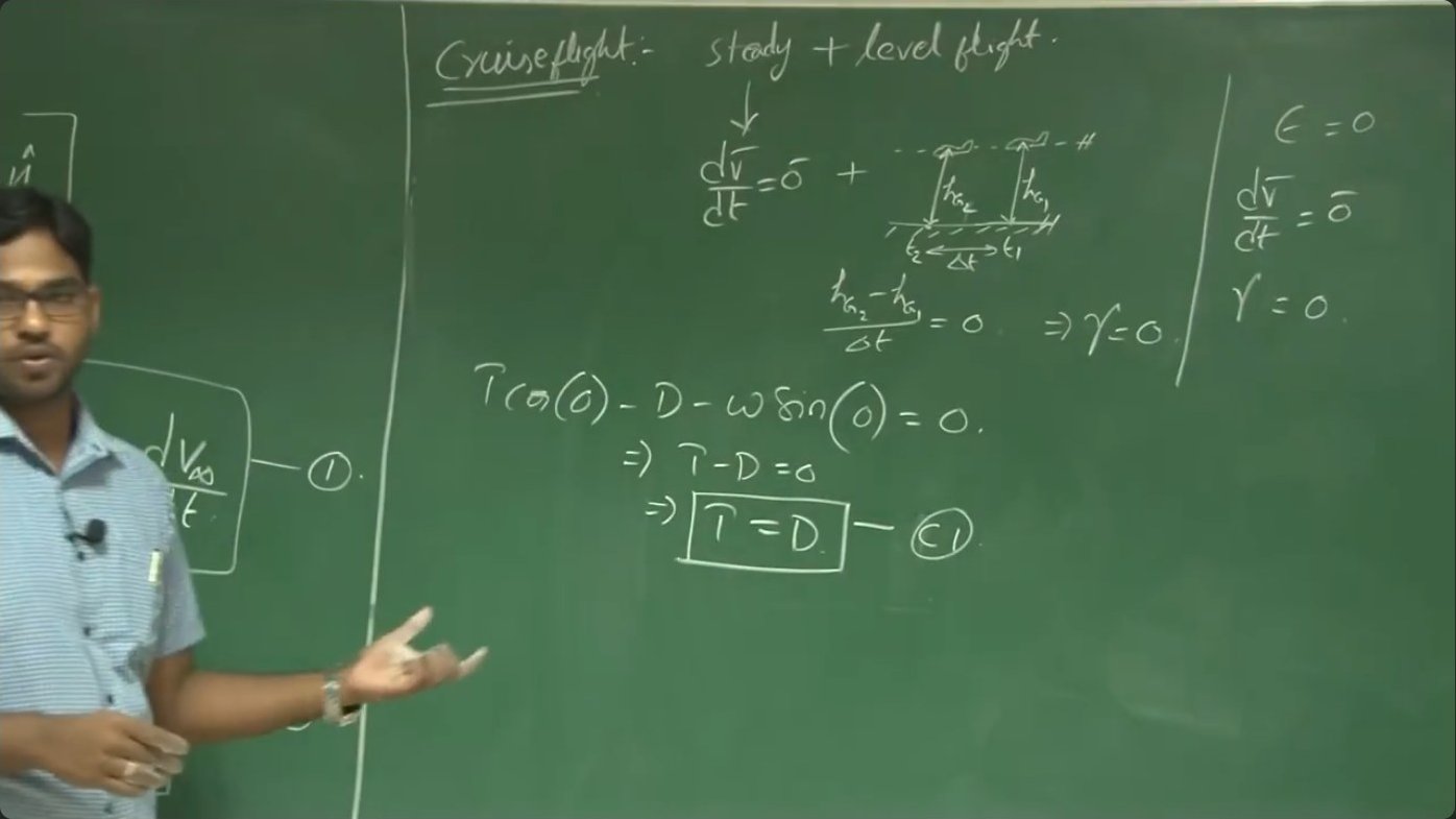
Steady level flight represents the most common operational mode for most aircraft missions. Steady means constant velocity—zero acceleration. Level means the altitude remains constant over time, which requires the flight path angle to be zero. When these conditions apply, the equations of motion simplify dramatically.
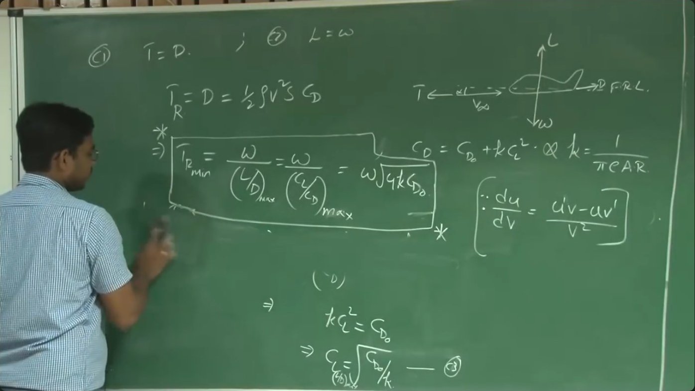
With zero flight path angle and no thrust misalignment, the parallel component equation reduces to thrust equals drag. The perpendicular equation yields lift equals weight. These two equilibrium conditions define the requirements for maintaining altitude at constant speed: the engine must produce thrust exactly matching drag, and the wing must generate lift exactly balancing weight.
Minimum Thrust Requirement
For level flight, thrust required equals drag, which can be expressed as the aircraft weight divided by the lift-to-drag ratio. Since drag comprises profile drag plus induced drag, the total drag coefficient is CD₀ + k CL², where k equals 1/(π e AR), incorporating Oswald efficiency and aspect ratio. This relationship means drag varies with both velocity and lift coefficient.
The minimum thrust occurs when the lift-to-drag ratio reaches its maximum. Calculus reveals this happens when the lift coefficient equals √(CD₀/k). At this condition, profile drag exactly equals induced drag, and the total drag coefficient is 2CD₀. The maximum lift-to-drag ratio equals 1/√(4k CD₀).
Substituting into the thrust equation yields the minimum thrust required as weight times √(4k CD₀). This represents the smallest engine output capable of sustaining level flight. Designing the mission profile around this minimum reduces fuel consumption and extends endurance—critical for unmanned systems with limited energy capacity.
Velocity for Minimum Thrust
Knowing the lift coefficient for minimum thrust allows calculation of the corresponding velocity. Since lift must equal weight, 1/2 ρ V² S CL = W. Solving for velocity gives V = √(2W/S)/(ρ CL). Wing loading W/S, air density ρ, and lift coefficient CL together determine flight speed.
Substituting the optimum lift coefficient CL = √(CD₀/k) yields the velocity for minimum thrust: V = √(2W/S)/ρ × (k/CD₀)^(1/4). This expression shows that minimum thrust speed increases with wing loading and decreases with air density. At higher altitudes where density is lower, the aircraft must fly faster to generate sufficient lift, increasing the minimum thrust requirement.
The Thrust-Velocity Relationship
Thrust required varies with velocity in a characteristic U-shaped curve. At very low speeds, induced drag dominates and thrust requirement is high. As speed increases, induced drag decreases but profile drag rises. The minimum point on this curve occurs at the velocity previously calculated.
The complete thrust-required expression can be written as T_R = 1/2 ρ V² S CD₀ + 2k W²/(ρ S V²). The first term increases with velocity squared while the second decreases with velocity squared. This creates the characteristic curve with a single minimum.
Rearranging this into a quadratic equation reveals an important property: for any thrust requirement above the minimum, two velocities satisfy the equilibrium condition—one slower and one faster than the minimum-thrust velocity. This mathematical fact has profound implications for flight safety and stability.
Mission Profile Considerations
A typical unmanned aircraft mission involves takeoff, climb, cruise, descent, and landing. Each phase imposes different power demands, but cruise typically dominates the time budget. A surveillance UAV might climb for two minutes and cruise for two hours. The ratio of cruise time to other flight phases often exceeds ten-to-one.
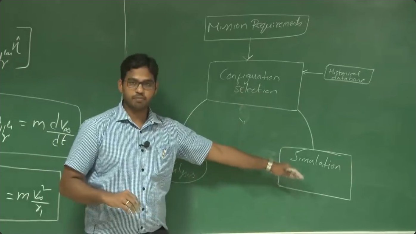
This time distribution means aircraft designers must optimize for cruise performance. Wing sizing, engine selection, and fuel capacity all depend primarily on cruise requirements. Mission range and endurance during the cruise phase drive the fundamental design decisions. Understanding thrust requirements for level flight is therefore central to the entire design process.
Flight Stability at Different Velocities
When two velocities provide the same thrust requirement, stability differs dramatically between them. Consider the aircraft trimmed at some velocity with the throttle set to match thrust required. A gust momentarily increases speed. On the back side of the thrust curve—slower than minimum-thrust velocity—this increase reduces thrust required below what the engine produces. The excess thrust accelerates the aircraft further from equilibrium.
Conversely, if a gust decreases speed on the back side, thrust required increases above engine output. Insufficient thrust decelerates the aircraft further. Both disturbances diverge from equilibrium. The pilot must constantly correct the throttle to maintain altitude—this region is unstable.
The front side of the curve—faster than minimum-thrust velocity—behaves oppositely. A speed increase raises thrust required above engine output, slowing the aircraft back toward equilibrium. A speed decrease lowers thrust required, allowing excess thrust to restore the original velocity. The aircraft naturally returns to its trim condition without pilot input. This region is stable.
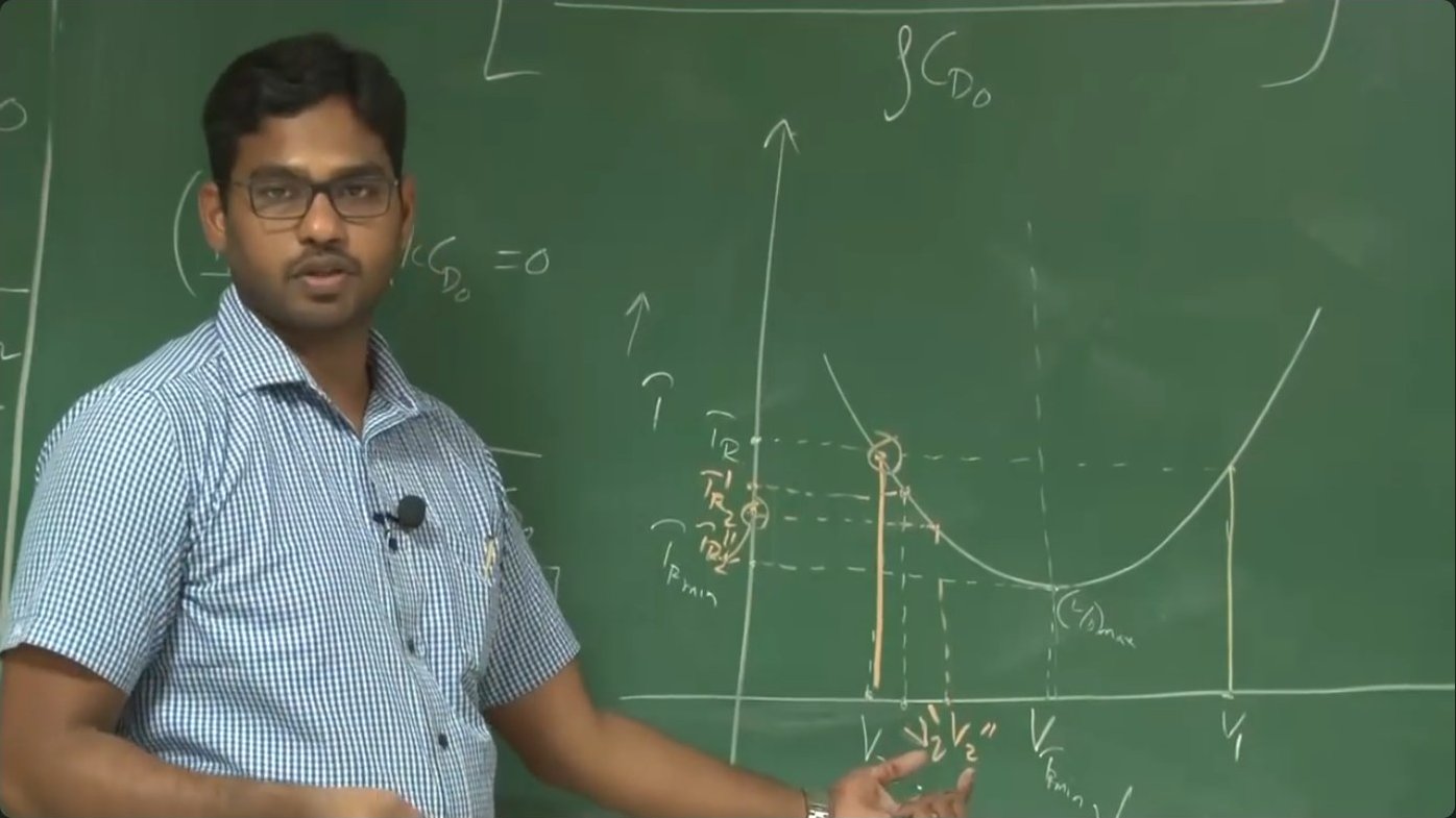
This stability analysis reveals why aircraft typically cruise well above minimum-thrust velocity despite the efficiency benefits. The inherent stability of the front-side regime reduces pilot workload and improves safety margins, especially important for remotely piloted systems where control latency can delay corrective inputs.
Designing for Cruise Performance
Sizing an aircraft wing begins with determining the design lift coefficient for cruise. This choice depends on the desired cruise velocity, which must balance efficiency against mission requirements. Flying at minimum thrust maximizes endurance for a given fuel load, but might not provide adequate speed to reach distant targets within acceptable time windows.
The design process starts with mission requirements: range, endurance, payload capacity, and operational altitude. Historical data informs initial configuration selection—wing planform, fuselage geometry, tail sizing. Performance analysis checks whether the configuration meets requirements. Iteration refines the design until all constraints are satisfied.
Once the design lift coefficient is selected, wing area follows from the requirement that lift equals weight: S = 2W/(ρ V² CL). Higher design lift coefficients allow smaller wings, reducing weight and drag. However, operating too close to maximum lift coefficient leaves insufficient margin for maneuvering or handling gusts. Typical cruise lift coefficients range from 30% to 50% of maximum.
Key takeaways
- → For steady level flight, thrust must equal drag and lift must equal weight, establishing the fundamental equilibrium conditions.
- → Minimum thrust requirement occurs when the lift-to-drag ratio is maximized, which happens when profile drag equals induced drag.
- → The optimum lift coefficient for minimum thrust equals √(CD₀/k), where k incorporates wing aspect ratio and Oswald efficiency.
- → Any thrust above the minimum corresponds to two possible velocities: one slower and one faster than the minimum-thrust velocity.
- → Flight faster than minimum-thrust velocity is inherently stable—disturbances self-correct without pilot input.
- → Flight slower than minimum-thrust velocity is unstable and requires constant throttle corrections to maintain equilibrium.
- → Aircraft design optimizes primarily for cruise performance since cruise dominates the mission time budget for most unmanned systems.